Calibration Target Types: Which One Do You Need?
Camera calibration is a process commonly used in machine vision that allows us to estimate important camera properties, which can be used to measure objects within images using real-world coordinates and account for imperfections in our camera system, such as lens distortion. The calibration process is based on a mathematical model, the pinhole camera model, which establishes a correspondence between the points of the 2D image plane and their projection in the 3D world, taking into account the geometric transformations involved and considering the intrinsic and extrinsic parameters of the camera.
To determine the camera's parameters, it is necessary to have the real-world points of an object and their corresponding image points. Using a calibration pattern with known geometry and dimensions provides this essential ground truth, allowing us to estimate the properties of the camera that was used to capture the images.
These calibration patterns are well-defined geometric patterns that usually have high contrast and uniform spacing, characteristics that make them easy to process using computer vision techniques. These algorithms can identify patterns based on their structure, obtain the location of distinctive points called "features" and then use the 2D-3D correspondences to calculate the camera’s parameters.
Because these patterns are highly customizable, there are infinite options to choose from, making the process of selecting the right one for an application quite challenging. This blog aims to simplify this process by describing and comparing the most popular patterns.
Pattern Types
While calibration patterns can be adjusted to specific needs, we will focus on the most commonly used pattern types, and describe their advantages and disadvantages, as well as their ideal use cases.
Checkerboard / Chessboard
- Description: Black and white alternating squares.
- Advantages:
- Easy to detect and analyze.
- Widely supported in libraries like OpenCV and MATLAB.
- Disadvantages:
- Not robust against occlusions or lighting changes.
- Requires the board to be perfectly flat.
- Image noise can lead to inaccurate corner detections.

- Note: To avoid 180-degree ambiguity, one side of the pattern should have an even number of squares and the other an odd number.
- Ideal Use Case: Calibration in controlled environments, such as laboratories.
Dot / Circle Pattern
- Description: Circles or dots arranged in a grid.
- Advantages:
- Robust against noise or blur in images.
- Provides accurate measurements, making it suitable for high-accuracy applications.
- Circle grids are highly customizable. They can be designed with symmetrical or asymmetrical layouts, inverse background color, uniform or non-uniform dot densities, filled or hollow circles, or even holes instead of circles.

- Disadvantages:
- Not robust against occlusions or lighting changes.
- Requires the board to be perfectly flat.
- A customized pattern may require special algorithms for detection.
- Symmetrical grids can’t be used to calibrate stereo cameras due to 180-degree ambiguity.
- Ideal Use Cases:
- Calibrating systems with significant lens distortion such as those used in aerial photogrammetry.
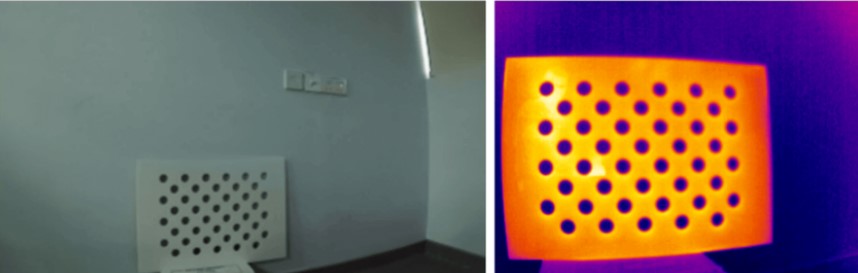
- Using boards with circular holes to calibrate thermal cameras
Coded / Fiducial Markers
ArUco Markers
An ArUco marker is a visual fiducial system that consists of a square with a black border and an internal binary matrix that encodes a unique ID. ArUco markers are organized into dictionaries that use the following format:
DICT_[X]X[X]_[Y]
Where [X]X[X] indicates the size of the internal binary matrix, and [Y] indicates the total number of unique marker IDs that the dictionary can generate.

Therefore, "DICT_5X5_250" means a dictionary of ArUco markers with a 5x5 grid of black and white squares or “bits”, and 250 unique markers.
AprilTags
AprilTags are 2D bar-coded markers with a black border and an internal binary code. They are organized into tag families that use the format:
Tag[XX][YY]
Where [XX] indicates the size of the tag's data bits and [YY] represents the error correction code used within the family.

For example, "Tag36h11" means the tag's internal binary code is 36 bits, and "h11" is the specific error correction code name.
ArUco markers and AprilTags have error correction schemes that incorporate a specific minimum hamming distance between codes, which allows for robustness against partial occlusions and lighting variations, making them suitable for dynamic environments. Their unique codes also allow for precise pose estimation and localization, making them extremely useful in applications like robotics and augmented reality.


ChArUco Board
- Description: Grid of black and white squares with embedded ArUco markers within the white squares.
- Advantages:
- The unique codes provide additional reference points.
- Designed to be able to detect and correct errors.
- Resistant to partial occlusions and lighting changes.
- Disadvantages:
- The pattern is more complex to generate and detect than a standard checkerboard.
- Ideal Use Cases:
- Outdoor environments: Camera calibration in dynamic outdoor settings.
- Augmented Reality: Its precise pose estimation allows for superimposing virtual elements in the real world.
- Multi-Camera Systems: Useful for calibrating stereo cameras.

AprilGrid
- Description: AprilTags arranged in a grid structure, with black squares at the corners of each tag as spacing.
- Advantages:
- Incorporates error correction.
- Robust to occlusions and lighting variations.
- Each tag within the grid has four keypoints used in calibration, making this pattern the most space-efficient option.
- Disadvantages:
- Requires software capable of AprilTag detection.
- Ideal Use Cases:
- Camera Network Calibration: Synchronizes multi-camera systems (e.g., surveillance, sports tracking).
- UAVs & SLAM: Serves as aerial landmarks for drones, allowing precise localization and mapping.
- Warehouse Automation: Guides autonomous mobile robots via floor/ceiling-mounted grids.


Checkerboard Marker Targets
- Description: It is based on a standard checkerboard but contains three circles in the center that act as absolute reference points.
- Advantages:
- Allows detection even in partially occluded images, as long as the reference circles remain visible.
- Enables robust detection with fewer pixels compared to a ChArUco board, allowing for denser patterns that contain more feature points.
- Disadvantages:
- Requires software capable of its detection.
- Ideal Use Case:
- This type of pattern could be useful in situations where a standard checkerboard would be insufficient due to potential occlusions, but the complexity of coded patterns is not desired.

PuzzleBoard
- Description: Variation of a checkerboard that instead of squares uses shapes that resemble puzzle pieces.
- Advantages:
- Robust against occlusions and warping.
- Can be decoded at very low resolutions.
- The decoding algorithm includes error correction and is computationally efficient.
- Disadvantages:
- Requires specialized algorithms to identify and decode these patterns.
- Ideal Use Case:
- Calibration of cameras with low resolution.


Halcon Targets
- Description: Grid of solid circles with strategically placed hollow circles serving as reference points.
- Advantages:
- Optimized for HALCON's calibration algorithms, ensuring high accuracy.
- Allows for precise subpixel feature localization.
- Disadvantages:
- Requires MVTec HALCON software for optimal use and feature detection.
- Ideal Use Case:
- Camera calibration for metrology, industrial inspection, and other high-precision applications.
Customizing Calibration Targets for Advanced Applications
We have now explored the most frequently used calibration patterns, each with its own strengths and limitations that determine whether or not they are appropriate for a given application. However, it is also possible to further adapt these standard designs for more complex scenarios by arranging them differently or incorporating new materials.
For example, it is possible to incorporate retroreflective tape over a pattern that allows for partial occlusions, such as an AprilGrid or a ChAruco board, to calibrate a camera-LiDAR system simultaneously.


For applications that require robust pose estimation, coded patterns like AprilTags can be arranged in a 3D structure to provide multi-directional feature points. These volumetric targets are useful for robot navigation, pick-and-place tasks, or multi-camera alignment, a technique commonly used in applications like industrial inspection and special effects in Hollywood.


Similarly, these patterns can be arranged as multi-plane targets or designs that provide a wider field of view to calibrate systems that need accurate 3D reference points. This configuration provides features that are visible from various angles, enabling sensor fusion in complex systems such as robot heads, where precise spatial relationships between the components are crucial.


When choosing between planar and volumetric calibration targets, it is important to consider the scope of the application. Planar targets, such as checkerboards or dot grids, are ideal for simpler applications and basic camera calibration; whereas volumetric targets are better suited for applications where it is required to know the orientation of the cameras relative to the environment, for example, in fields like robotics or 3D reconstruction.
This flexibility makes calibration targets adaptable to diverse fields, ranging from multi-camera synchronization in surveillance to warehouse automation with robot swarms. These patterns can be tailored to match the requirements of the application by simply changing the type, size, and pattern density, or adjusting the layout and materials used to ensure optimal performance even in complex applications.
Leave A Reply