Camera Calibration 101: Practical Tips, Tools & Troubleshooting
Camera calibration is a method that uses images of a known pattern to estimate the internal characteristics of the camera used to acquire them. The calibration algorithm is based on a mathematical model, the pinhole camera model [link to the second blog], which allows us to calculate the camera's intrinsic parameters associated with the lens and image sensor, as well as the distortion coefficients which can be used to undistort the image and obtain precise measurements of objects in the real world.
Calibration is an essential first step in digital image analysis, as a calibrated camera will provide more accurate measurements. However, it can only be as precise as the procedure and tools employed, which is why we need to be meticulous when preparing our setup to achieve optimal results.
In this blog, we will discuss the best practices to achieve accurate camera calibration, and explore software tools that help with the necessary mathematical calculations as well as techniques to evaluate our results and improve the performance of our calibration.
Steps for Camera Calibration
2. Measure the physical dimensions of the squares or markers. Precision is crucial for accurate results so it is advisable to use calipers.
3. Capture at least 10 to 20 images of the pattern at different angles, distances, and coverage.
4. Load the images in a computer vision tool such as OpenCV, MATLAB, ROS, or any other software that can detect the patterns and calculate the camera's parameters.


Best Practices
Setup
- Use a fixed focus and do not change the zoom; if these settings change either throughout or after calibration, the focal length can vary, invalidating it.
- Use a fixed exposure setting; auto-exposure can also invalidate the results of your calibration.
- The camera must be calibrated at the desired resolution. Although distortion coefficients are resolution-invariant given a fixed aspect ratio and FOV, the intrinsic camera parameters will match your system's chosen resolution.
- Have a controlled lighting source, preferably diffuse, to minimize shadows.

Target Specifications
- For the highest accuracy, prioritize vector formats like PDF or SVG.
- Always ensure that no scaling is applied during printing.
- The print quality of the calibration board should be high, especially for precision applications. Look for high contrast and low manufacturing tolerance.
- Use a material that is flat, non-reflective, and as rigid as possible.
- The calibration pattern should cover at least 50% of the frame, ideally 80% when seen parallel to the camera at your working distance.
- Ensure that the pattern has a white border around it. Ideally, the border should be as large as one grid element of the pattern to minimize false feature detections on the background.

Image Capturing Tips
- Capture the images at a distance close to the one you will use in your application.
- For most applications, it is best to keep the camera fixed and move the target to prevent camera shake. In this case, it is recommended to use a stable tripod and avoid touching the camera to prevent blurry images.
- For applications that use a large target, moving it can be challenging or may lead to deformations; in this case, it is more practical to move the camera instead.
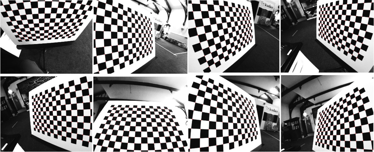
- Take a wide variety of images at different orientations relative to the camera.

- Take at least one close-up fronto-parallel image that completely covers the frame, and try to include as many of the features in the view as possible. Radial distortion is more noticeable near the edges; to capture this, the image should show features in areas near the edges.

- A large amount of your image set, ideally 50% or more, should emphasize the effect of foreshortening, which makes closer markers appear larger than those far away. To achieve this, place the pattern at an angle, preferably up to +/- 45 degrees relative to the camera plane.

- Account for as much of the frame as possible; this will ensure that you get even coverage of the lens with your image set.
- Merging the last two considerations, we suggest capturing an image with the edge of the target as close as possible to one of the sides of the frame and moving the opposite edge away from the center, tilting no more than 45 degrees. Repeat this for each side of the image as well as each corner.
- Once these views are covered, we can capture more images to increase accuracy, however, it is important not to use the same perspective more than once to avoid overfitting.
- Use uncompressed images or images in lossless compression formats, such as PNG.
- Do not crop or modify the images before uploading them to the calibration software.
- When using a wide-angle lens, consider adjusting the software settings to estimate more than 2 radial distortion coefficients.
- For complex camera systems, it is also advisable to factor in tangential distortion and pixel skew.
- For calibrating stereo cameras, place the target in different positions where the pattern is fully visible from both cameras.
- When using fisheye lenses make sure to use a specialized model, for example, OpenCV’s fisheye model or MATLAB's fisheye calibration module.
Calibration Software

The reprojection error is the difference between the detected features and their corresponding projected image points. It allows us to measure how accurate the found parameters are; the lower the reprojection error, the more reliable the estimated parameters.
Although the reprojection error is a good qualitative reference, obtaining a low value does not necessarily mean that we achieved a good calibration, as it only indicates that the data provided can be described with the estimated model. A possible reason for bad calibration performance could be due to overfitting, for example, if all your calibration images are taken from a very similar distance and angle, the reprojection error can be low and calibration might be very accurate for a specific viewpoint, but perform poorly for others.

How to Validate Accuracy and Improve Calibration Results
Another option is to carefully inspect the detected feature positions in all images to identify and remove any outliers (false detections).


These views also allow you to check whether the image set achieved sufficient coverage of the field of view. However, for this, there are also other options, such as using the open-source tool mrcal.
For optimal results, ensure the dataset provides full coverage. If you are able to spot any noticeable gaps it is important to capture additional images of the missing views to achieve reliable calibration.

Leave A Reply