The Science Behind Camera Calibration in Machine Vision
However, images captured by vision systems have a 2D coordinate frame in pixels, while the 3D location of objects in the world is described by units such as inches or millimeters. The pinhole camera model links these two coordinate frames, by allowing us to mathematically represent the conversion of the position of real-world points to their projection in image space.
Pinhole Camera Model


Intrinsic and Extrinsic Parameters


Where s is an arbitrary scale factor of the projective transformation.
Finally, the complete projection matrix P is a combination of both the intrinsic parameter matrix A and the extrinsic parameter matrix [R t]:


Distortion
We have now studied the ideal mathematical model, however in the real world lenses tend to introduce some distortion to images, these are caused by defects in their design that generate deviations from the "perfect" pinhole model. Nevertheless, distortion is an optical aberration that does not lose the information in the image but simply misplaces it geometrically. This means that we can remove distortions from an image if we consider their influence on our camera model.
Note: Lenses with larger FOVs, such as the fisheye lens, will introduce extreme distortions, because of this the pinhole camera model cannot be used with a fisheye camera.
To accurately represent a real camera system we can complete the model by including radial and tangential distortions:
- Radial distortion: occurs when light rays bend more near the edges of a lens than at its optical center causing straight lines to appear curved at the edges of an image. There are two types of radial distortions: pincushion (positive displacement) and barrel (negative displacement).


Where x and y are the undistorted locations in normalized image coordinates, which are pixel coordinates translated to the optical center and divided by the focal length, and k1, k2, and k3 are the radial distortion coefficients.
Note: For real lenses radial distortion is always monotonic, which means that the coefficients consistently increase or decrease, if the calibration algorithm produces a non-monotonic result it should be considered an error in the calibration.
- Tangential distortion: occurs when the lens and the image plane are not aligned perfectly parallel causing some areas in the image to look closer than others.


Tangential distortion can be represented as:

Where p1 and p2 are the tangential distortion coefficients.
In summary, we need to calculate five distortion parameters to remove the distortion from our image: k1, k2, k3, p1, and p2. These coefficients do not depend on the scene viewed which is why they can also be considered intrinsic camera parameters.
Note: In practice, it is enough to consider only two radial distortion coefficients for calibration. However, for extreme distortion, such as when using wide-angle lenses, it is recommended to use three coefficients.
Camera Calibration
Now, we have a model that can calculate the location of a real-world object from the images acquired by a camera, but to use it we need to know the camera’s parameters, which might not be available. However, we do have access to the images the camera takes which means that if we took pictures of a known object we could estimate the camera’s parameters based on the object’s projection onto the image plane. This process of finding the intrinsic and extrinsic camera parameters is known as camera calibration.

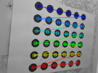
To estimate the camera parameters, we need to have the 3D world points of an object and their corresponding 2D image points. This is why the traditional way to calibrate a camera is to use a reference object of known geometry to use as ground truth. This is where calibration targets come in handy as they have specific patterns that through image analysis techniques can be processed to easily obtain the location of pattern features. These features may correspond to the intersection of vertical and horizontal lines in a checkerboard or the center of circles when the calibration board is a dot pattern.

Why Checkerboards, Circles, and Dot Patterns are used for Calibration
Checkeboards and dot grids provide high contrast by alternating black and white markers (squares or circles) making feature detection robust, as even in varying lighting conditions the sharp color transitions can be accurately detected providing a high level of precision in locating feature points.
Additionally, the geometric regularity imposes constraints that algorithms can use to refine the detected points by ensuring alignment with the expected pattern. This predictability helps to identify and discard outliers (false detections) as instead of treating each feature as independent, the regularity of the pattern can be used with global optimization techniques. Moreover, the uniform spacing in the pattern helps to identify lens distortions by analyzing how the lines or points deviate from their expected positions.


These patterns are also very easy to customize by simply changing their size or pattern density. This adaptability has made them widely used in the community, and the simplicity of their analysis has made them a standard for calibration tools making them universally supported in popular computer vision libraries such as OpenCV and MATLAB. However, to achieve an accurate camera calibration it is recommended to tailor these patterns to your specific use case using a custom pattern generator. This combined with a high-quality printing service, ensures optimal results by balancing the flexibility of these patterns with rigorous production standards.
Leave A Reply